


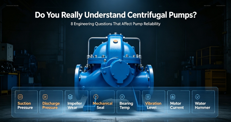
A reliable centrifugal pump system depends on more than just selecting the right pump.
The suction piping, discharge piping, valves, system layout, and operating conditions can all have a significant impact on pump performance, stability, and service life.
Below are 8 common engineering questions about centrifugal pump piping and operation.
Ø Q1: Why is the suction pipe usually one size larger than the pump suction nozzle?
This is a very common practice in centrifugal pump installations.
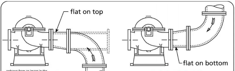
In many applications, the nominal diameter of the suction pipe is selected one size larger than the pump suction nozzle. A suitable eccentric reducer is normally used to connect the pipe to the pump.
Why?
There are three main reasons:
1. Lower suction velocity
A larger suction pipe reduces the liquid velocity and therefore reduces friction and pressure losses in the suction line.
This helps maintain a higher pressure at the pump suction.
2. Better NPSH conditions
Lower suction-side pressure loss means higher pressure available at the pump inlet, which helps improve the available NPSH (NPSHa) and reduce the risk of cavitation.
3. Better flow conditions at the pump inlet
The pump does not only need sufficient liquid at the suction inlet. It also needs a stable and reasonably uniform flow pattern.
An elbow, tee, valve, or other disturbance installed too close to the pump suction can create turbulence, swirl, and uneven velocity distribution.
For this reason, sufficient straight pipe length should normally be provided upstream of the pump.
Why is an eccentric reducer commonly used?
For horizontal suction piping, a flat-on-top eccentric reducer is commonly used to minimize the possibility of air pockets forming in the suction line.
However, this is not an absolute rule for every installation.
The reducer orientation should be determined based on the pump arrangement, piping slope, liquid characteristics, and the possibility of air accumulation.
Engineering principle
The goal is not simply to make the suction pipe “one size larger.”
The design should consider:
- · Suction velocity
- · Friction and local pressure losses
- · NPSHa
- · Pump inlet flow pattern
- · Straight pipe length
- · Location of elbows and valves
- · Possibility of air pockets
Ø Q2: Why is a control valve often smaller than the main pipe?
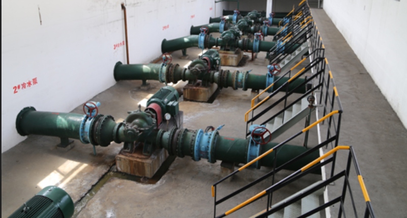
Unlike suction piping, control valves are not always selected with the same nominal diameter as the main pipeline.
For example:
There are several reasons for this practice.
1. Lower cost
A smaller valve generally costs less than a valve with the same diameter as the main pipeline.
2. Better control range
A control valve regulates flow by changing its opening.
If the valve is oversized, it may operate at a very small opening under normal conditions. This can reduce its effective control range and make precise flow control more difficult.
A properly sized smaller valve can operate within a more suitable opening range.
3. The trade-off is higher pressure loss
A smaller valve increases flow velocity and therefore increases pressure drop.
So the principle is not:
The valve should be properly selected based on:
- · Flow rate
- · Differential pressure
- · Cv/Kv
- · Required control range
- · Allowable pressure drop
Ø Q3: Does a centrifugal pump suction inlet always need positive pressure?
No.
A common misconception is that the suction pressure of a centrifugal pump must always be above atmospheric pressure.
In reality, many pumps can operate with the liquid level below the pump centerline, allowing the pump to lift liquid from below.
However, the key issue is not simply whether the pump can “lift” the liquid.
The actual system must satisfy the required NPSH condition:
As the suction lift increases, the pressure at the pump inlet decreases and the suction line losses become more significant.
Therefore, the higher the suction lift, the more carefully the system should be checked for cavitation risk.
Ø Q4: Is a check valve required on the pump discharge side?
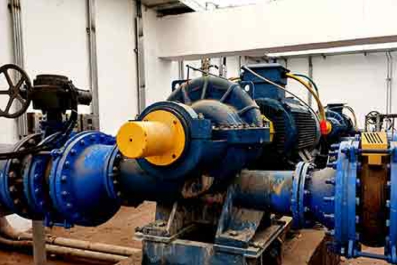
In many pumping systems, a discharge check valve is an important part of the system design.
It mainly provides three benefits.
1. Prevents reverse flow
When the pump stops, pressure differences in the system can cause liquid to flow back toward the pump.
The check valve prevents this reverse flow.
2. Prevents reverse rotation
Reverse flow can cause the pump impeller to rotate backward.
Depending on the pump and driver arrangement, this may cause problems with:
- · Mechanical seals
- · Bearings
- · Couplings
- · Motor or other drive equipment
3. Helps maintain a filled pipeline
In some systems, maintaining liquid in the discharge line is important for reliable restart and system operation.
However, the valve type, installation position, and closing characteristics should be selected according to the actual system.
For systems sensitive to water hammer, additional measures such as non-slam check valves, slow-closing check valves, air valves, or surge protection devices may be required.
Ø Q5: What is the ideal piping layout for a centrifugal pump system?
Pump instability is sometimes caused not by the pump itself, but by poor piping arrangement.
One common problem is:
Ideally
In certain pumping systems, the discharge pipeline should rise continuously toward the receiving tank or system destination.
This allows air entering the system to move toward the high point and eventually escape.
A simplified ideal arrangement is:
What happens in real projects?
In real installations, pipelines often include long horizontal sections.
A long horizontal section is not necessarily a problem.
The key is to avoid unnecessary:
- · High points
- · Low points
- · Reverse slopes
- · Locations where air can accumulate
If a high point cannot be avoided, an appropriate air release valve / air valve may be required.
What if a control valve is installed near the end of the pipeline?
The location of the control valve should be considered together with the tank level, downstream pressure, valve pressure drop, and cavitation risk.
The system should maintain sufficient pressure at the valve and avoid operating conditions that could lead to cavitation.
The basic principle is:
Ø Q6: How can you check pump performance in the field?
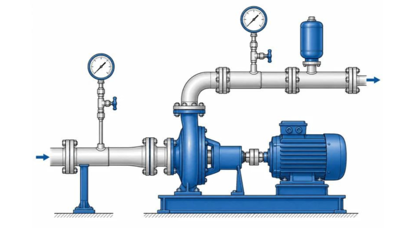
One of the most reliable methods is to compare actual field measurements with the manufacturer’s pump performance curve.
Typical measurements include:
- · Flow rate
- · Suction pressure
- · Discharge pressure
- · Pump speed
- · Elevation difference between the pressure measurement points and the pump centerline
Where should pressure gauges be installed?
Pressure gauges should be installed as close as practical to the pump suction and discharge nozzles.
The elevation difference between the pressure measurement points and the pump centerline should also be recorded.
The pump head is not simply:
The calculation should also consider elevation difference and, where relevant, velocity effects.
How can flow rate be measured?
Ideally, use a suitable flow measurement device such as:
- · Magnetic flow meter
- · Ultrasonic flow meter
- · Turbine flow meter
- · Other appropriate flow measurement equipment
If a flow meter is not available, flow can sometimes be estimated by measuring the time required to fill a tank of known volume.
Can we check only the shut-off head?
Yes, for a basic performance check.
The shut-off head occurs at zero flow, so no flow measurement is required.
Comparing the measured shut-off head with the manufacturer’s curve can help identify whether:
- · The pump is running at the correct speed
- · The correct impeller diameter is installed
- · The pump performance is generally consistent with the expected curve
However:
Zero-flow operation can cause overheating, internal recirculation, mechanical seal damage, and other problems.
What about pump efficiency?
Efficiency measurement is more complicated because the input power to the pump shaft must be determined accurately.
In field testing, this may involve measuring motor input power and accounting for motor and transmission efficiency, or directly measuring shaft torque and speed.
Ø Q7: How does liquid viscosity affect centrifugal pump performance?
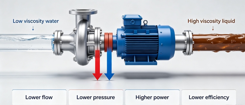
Most centrifugal pump performance curves are based on testing with clean water under standard conditions.
When the pumped liquid has a significantly higher viscosity than water, pump performance can change considerably.
Typical effects include:
- · Lower flow
- · Lower head
- · Lower efficiency
- · Higher power requirement
Therefore:
The actual liquid viscosity, density, temperature, and operating point should be considered.
For highly viscous liquids, the efficiency of a centrifugal pump may decrease significantly.
Depending on the application, positive displacement pumps, such as screw pumps, gear pumps, or rotary pumps, may provide a better solution.
There is no single viscosity value that can be used as a universal limit for every centrifugal pump. The suitability of the pump should be evaluated based on the actual application and pump design.
Q8: Can a pump operate anywhere within the flow range shown on its performance curve?
Not necessarily.
The fact that a point appears on the pump curve does not mean it is a suitable point for continuous operation.
A centrifugal pump should normally operate as close as practical to its:
Many applications target a normal operating range around 80%–120% of BEP flow, but the actual allowable operating range should always be based on the manufacturer’s recommended operating envelope.
Why should prolonged low-flow operation be avoided?
When the flow is significantly below BEP, the pump may experience:
- · Internal recirculation
- · Temperature rise
- · Increased radial loads
- · Higher vibration
- · Mechanical seal wear
- · Increased bearing loads
If continuous low-flow operation is unavoidable, possible solutions include:
Option 1: Minimum-flow bypass / recirculation line
A portion of the liquid is continuously returned to the suction source or another suitable location.
Option 2: Variable speed drive
A VFD can be used to reduce pump speed and better match the pump output to the actual system demand.
What about excessive flow?
Operating too far to the right of the pump curve can also create problems, including:
- · Higher NPSHr
- · Reduced NPSH margin
- · Cavitation
- · Increased vibration
- · Motor overload
- · Reduced efficiency
Therefore:
The preferred operating point is normally close to the design duty point and BEP, while remaining within the manufacturer’s allowable operating range.

Good pump engineering is not simply about selecting the right pump.
It is about creating a well-matched system in which the pump, piping, valves, driver, and operating conditions work together.
For centrifugal pumps, stable suction flow, adequate NPSH margin, properly sized piping, and operation near BEP are some of the most important factors for achieving reliable and long-term performance.
Post time: Sep-01-2026