


Achieving NFPA 20 compliance ensures a fire pump performs reliably during an emergency. The standard’s most critical requirements focus on four key areas for system integrity.
·Proper Pump Selection
·Secure Installation
·A Reliable Power Supply
·Regular Testing and Maintenance
This guide simplifies these complex standards into actionable steps. It provides clarity for the installation and upkeep of end suction centrifugal pumps, helping facilities maintain a constant state of readiness.
Step 1: Selecting the Right End Suction Fire Pump
Selecting the correct fire pump is the foundational step for NFPA 20 compliance. The pump must not only meet the hydraulic demands of the fire protection system but also carry the proper certifications and be constructed from durable materials. This ensures it will perform as expected during a fire emergency.
Verifying UL Listing and FM Approval
Third-party certification from Underwriters Laboratories (UL) and Factory Mutual (FM) Global provides assurance of a pump’s reliability and performance. Facility managers can confirm a pump’s certification through a clear, three-step process:
1.Request Certificates from the Manufacturer: The manufacturer provides official certificates detailing the pump assembly’s compliance with NFPA 20.
2.Verify with Official Online Databases: Cross-reference the model and file numbers in the UL Product iQ or FM Approval Guide online databases. A model not found in these directories is not certified.
3.Inspect the Pump’s Data Plate Markings: Upon delivery, check the pump’s permanent nameplate for the official certification mark, model number, and performance data. This information must match the certificate and online listing.
Understanding the Pump Performance Curve
The pump performance curve is a graph that defines a pump’s operational capabilities. NFPA 20 requires that a pump’s performance is verified at three critical points:
·Churn (0% Flow): The pressure when the pump operates with no water flowing. The shutoff pressure must stay within 101% to 140% of the rated pressure to avoid damaging system components.
·Rated Flow (100% Flow): The design point where the pump delivers its rated gallons per minute (GPM) at the rated pressure.
·Overload (150% Flow): The pump must deliver at least 65% of its rated pressure at 150% of its rated flow without overloading its driver (motor or engine).
The driver’s horsepower rating must be sufficient to handle the pump’s demand at every point along this curve.
Matching Materials of Construction to Standards
NFPA 20 specifies robust materials to ensure longevity and prevent premature failure. Standard end suction centrifugal pumps are typically built with a cast iron casing, a bronze or stainless steel impeller, and a high-strength stainless steel shaft.
Note for Corrosive EnvironmentsFor applications involving saltwater or corrosive liquids, standard materials are insufficient. NFPA 20 allows for specialized materials. For example, end suction centrifugal pumps intended for marine environments may use bronze, duplex stainless steel, or special coatings to resist corrosion and ensure reliable operation. Always consult the manufacturer for the correct material selection based on the water source.
Step 2: Critical Installation of End Suction Centrifugal Pumps
A correctly selected pump performs only as well as its installation. Proper installation of end suction centrifugal pumps ensures mechanical stability, hydraulic efficiency, and long-term reliability. NFPA 20 outlines specific requirements for the pump’s environment, foundation, and piping to guarantee it functions correctly during an emergency.
Pump Room and Foundation Requirements
The pump’s location and support structure are foundational to compliance. The pump room itself must meet strict criteria to protect the equipment and ensure accessibility.
·Construction: The room must be dedicated to fire protection equipment and separated from other areas by fire-rated construction.·
·Access: It requires direct access from the building’s exterior or through a fire-rated corridor, with doors large enough to move equipment.
·Environment: The room must maintain a minimum temperature of 40°F (4°C) to prevent freezing. Diesel-driven pumps also require robust ventilation systems to remove exhaust fumes and provide sufficient air for combustion.
The pump’s foundation must be substantial enough to absorb vibration and provide rigid support. It is typically made of reinforced concrete and must be designed to carry the full weight of the pump and driver assembly. The pump’s base plate is secured to the foundation with anchor bolts and then filled with grout, creating a single, solid structural unit that prevents movement and maintains shaft alignment.
Suction and Discharge Piping Arrangement
Proper piping is critical for preventing cavitation—a damaging condition caused by low pressure at the pump’s suction inlet. NFPA 20 provides clear rules for the suction pipe arrangement:
·The suction pipe must be at least as large as the pump’s suction flange.
·It should be as short and straight as possible.
·A straight section of pipe equal to at least 10 times the pipe’s diameter must be installed directly before the pump’s suction inlet to minimize turbulence.
·Elbows and fittings that create turbulence should be avoided near the pump inlet.
Discharge piping must also be correctly sized and securely supported to handle the high pressures generated by the pump. Both suction and discharge piping for end suction centrifugal pumps must be installed to prevent stress on the pump casing.
Required Gauges and Relief Valves
Instrumentation allows operators to verify the pump’s performance. NFPA 20 mandates pressure gauges on both the suction and discharge sides of the pump. These gauges must be located near the pump flanges for accurate pressure readings during testing and operation.
When is a Main Relief Valve Required?A main pressure relief valve is generally not permitted on electric motor-driven fire pumps. However, it is required for diesel engine-driven pumps if the maximum pressure could exceed the rating of the system components. This can happen if the engine runs too fast or if high static suction pressure exists. The valve is sized according to NFPA 20 tables and is set to open before system pressure becomes dangerously high.
Step 3: Ensuring a Reliable Power Supply and Controller
A fire pump is only effective if it has a dependable power source and an intelligent controller to activate it. NFPA 20 establishes strict rules for the electrical and mechanical systems that support the fire pump, ensuring it runs without fail during an emergency. These requirements differ based on whether the pump uses an electric motor or a diesel engine driver.
Compliance for Electric Motor Drivers
Electric motor-driven pumps require a dedicated and robust power source. This supply must come from a reliable utility connection or an on-site power generation facility. The power feed must be separate from the building’s general electrical system to prevent interruption. All wiring and conduits must be protected from physical damage and fire. For example, feeder cables are often routed outside the building or encased in two inches of concrete to ensure their integrity.
Voltage Drop is CriticalThe power supply must be sized to handle the motor’s significant power draw during startup. NFPA 20 permits a voltage drop of no more than 15% when the motor is starting and no more than 5% when it is running at full load.
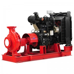
Compliance for Diesel Engine Drivers
Diesel engines provide a self-contained power source but require their own support systems. A key requirement is the fuel supply. The on-site fuel tank must hold enough diesel to run the pump for an extended period, typically calculated as 1 gallon per horsepower, plus an additional 10% volume for sump and expansion. The engine also needs a dedicated cooling system, which often uses a heat exchanger that circulates water from the pump’s discharge to keep the engine from overheating. Proper ventilation is also mandatory to provide fresh air for combustion and safely route exhaust fumes outside the pump room.
Fire Pump Controller Specifications
The fire pump controller is the brain of the system, responsible for automatically starting the pump when it detects a pressure drop. The controller must be located in the same room as the pump and be easily accessible. NFPA 20 mandates that the controller monitor and signal several critical conditions to a remote location. Key supervised alarms include:
·Pump is running
·Loss of primary power
·Phase reversal (for electric motors)
·Engine trouble or low fuel (for diesel engines)
These remote alarms ensure that building personnel are immediately aware of the system’s status, whether it is operating normally or requires attention.
Step 4: Acceptance Testing and Ongoing Maintenance
A compliant fire pump system requires verification of its performance upon installation and regular upkeep to ensure its readiness. Acceptance testing validates the initial setup, while a consistent maintenance schedule preserves the pump’s operational integrity for years to come.
The Field Acceptance Test Procedure
The field acceptance test is the final verification that the fire pump system performs as designed. This crucial test is conducted by qualified personnel, which may include the manufacturer’s representative, the fire protection contractor, and the Authority Having Jurisdiction (AHJ). During the test, technicians record pump pressures and flow rates at multiple points. The pump must meet or exceed the performance shown on its certified shop curve at three critical conditions: no-flow (churn), rated flow (100%), and peak flow (150%). For pumps with variable speed controls, testing expands to include measurements at 25%, 50%, 75%, and 125% of rated capacity.
Weekly and Annual Inspection Checklists
Regular inspections are mandatory for maintaining compliance and reliability.
·Weekly “No-Flow” Test: Facility personnel should run the pump for at least 10 minutes each week without flowing water. During this test, they record starting, suction, and discharge pressures. They also check for unusual noises, vibrations, or overheating in the pump casing and bearings. The pump packing glands should be inspected for proper leakage, which is typically a slow drip to ensure lubrication.
·Annual “Full-Flow” Test: A qualified technician must perform a comprehensive test annually. This test measures pump performance at no-flow, rated flow, and 150% of its rated capacity using calibrated equipment. The technician documents all raw data, including pressures, flow rates, voltage, and amperage, comparing the results to previous tests to identify any performance degradation.
Key Maintenance Tasks for Longevity
Proactive maintenance prevents unexpected failures and extends the pump’s service life. Two critical tasks are lubrication and packing adjustment.
Pro Tip: Lubrication and PackingMost end suction fire pumps use grease-lubricated bearings. The manufacturer’s guidelines dictate the re-lubrication schedule based on bearing size and operating hours. Technicians should also check the pump packing during weekly runs. Proper adjustment ensures a slight leakage for cooling and lubrication, preventing premature wear. Repacking becomes necessary only when the gland can no longer be adjusted to control leakage.
A facility’s compliance journey rests on four pillars: Correct Selection, Proper Installation, Reliable Power, and Regular Testing. Adherence prevents common inspection failures, such as poor flow test results or inaccessible gauges.
Final Compliance Checklist
·Pump is UL/FM listed.
·Performance is verified at 150% capacity.
·Piping is correctly sized.
·Power source is dedicated and reliable.
·All required tests are conducted.
Neglecting these steps can lead to severe legal fines and insurance claim denials. Facility managers should always consult the latest edition of NFPA 20, which is updated periodically, and a qualified professional like a certified fire protection engineer to ensure complete safety and compliance.
FAQ
Why is the 10-pipe-diameter rule for suction piping so important?
This rule ensures smooth, non-turbulent water flow into the pump. Turbulence can cause cavitation, a condition that damages the impeller and reduces performance. Adherence to this standard protects the equipment and guarantees reliability during an emergency.
Can a standard end suction pump be used for saltwater applications?
Standard pumps use materials that corrode in saltwater. NFPA 20 requires special, corrosion-resistant materials for these environments. Leading manufacturers like TONGKE offer pumps built with bronze or duplex stainless steel specifically for marine and other demanding liquid applications, ensuring longevity and compliance.
What is the purpose of the weekly “no-flow” test?
The weekly test verifies the pump’s readiness without flowing large water volumes. It confirms the pump starts correctly and allows operators to check for leaks, unusual vibrations, or overheating. This simple check is a key part of proactive maintenance and NFPA 20 compliance.
Does every fire pump need a pressure relief valve?
A main relief valve is typically required only for diesel engine-driven pumps. The valve protects system components from overpressure if the engine runs too fast. Electric motor-driven pumps, with their constant operating speed, generally do not require one.
Post time: Dec-12-2025