


Technical Specifications and Engineering Practice Analysis for the Installation of Eccentric Reducers at the Inlet of Centrifugal Pumps:
1.Principles for Choosing Installation Direction The installation direction of eccentric reducers at the inlet of centrifugal pumps should comprehensively consider the characteristics of fluid dynamics and equipment protection needs, primarily following the dual-factor decision model:
Priority for Cavitation Protection:
When the system’s Net Positive Suction Head (NPSH) margin is insufficient, a Top-Flat Orientation should be adopted to ensure that the bottom of the pipe continuously descends to avoid liquid accumulation that can lead to cavitation.
Liquid Discharge Requirements: When there is a need for condensate or pipeline flushing, a Bottom-Flat Orientation can be chosen to facilitate the discharge of the liquid phase.
2.the analysis of top flat installation technology
Advantages of Fluid Mechanics:
● Eliminates flexitank effect: Keeps the top of the tube continuous to avoid fluid stratification and reduces the risk of airbag build-up
● Optimized flow velocity distribution: Guides smooth fluid transitions and reduces turbulence intensity by about 20-30%
Mechanism of anti-cavitation:
● Maintain a positive pressure gradient: prevent the local pressure from falling below the saturated vapor pressure of the medium
● Reduced pressure pulsation: Eliminates vortex generation zones and reduces the probability of cavitation
International standards support:
● API 610 standard requires: Inlet eccentric parts should be preferentially installed on top level
● Hydraulic Institute Standard: Recommended for flat mounting as standard for cavitation resistance
3.Applicable scenarios for bottom-flat installation
Special working conditions:
● Condensate Discharge System: Ensures efficient discharge of condensate
● Pipe flushing circuit: facilitates sediment removal
Design Compensation:
● Exhaust valves are required
● The inlet pipe diameter should be increased by 1-2 grades
● It is recommended to set up pressure monitoring points
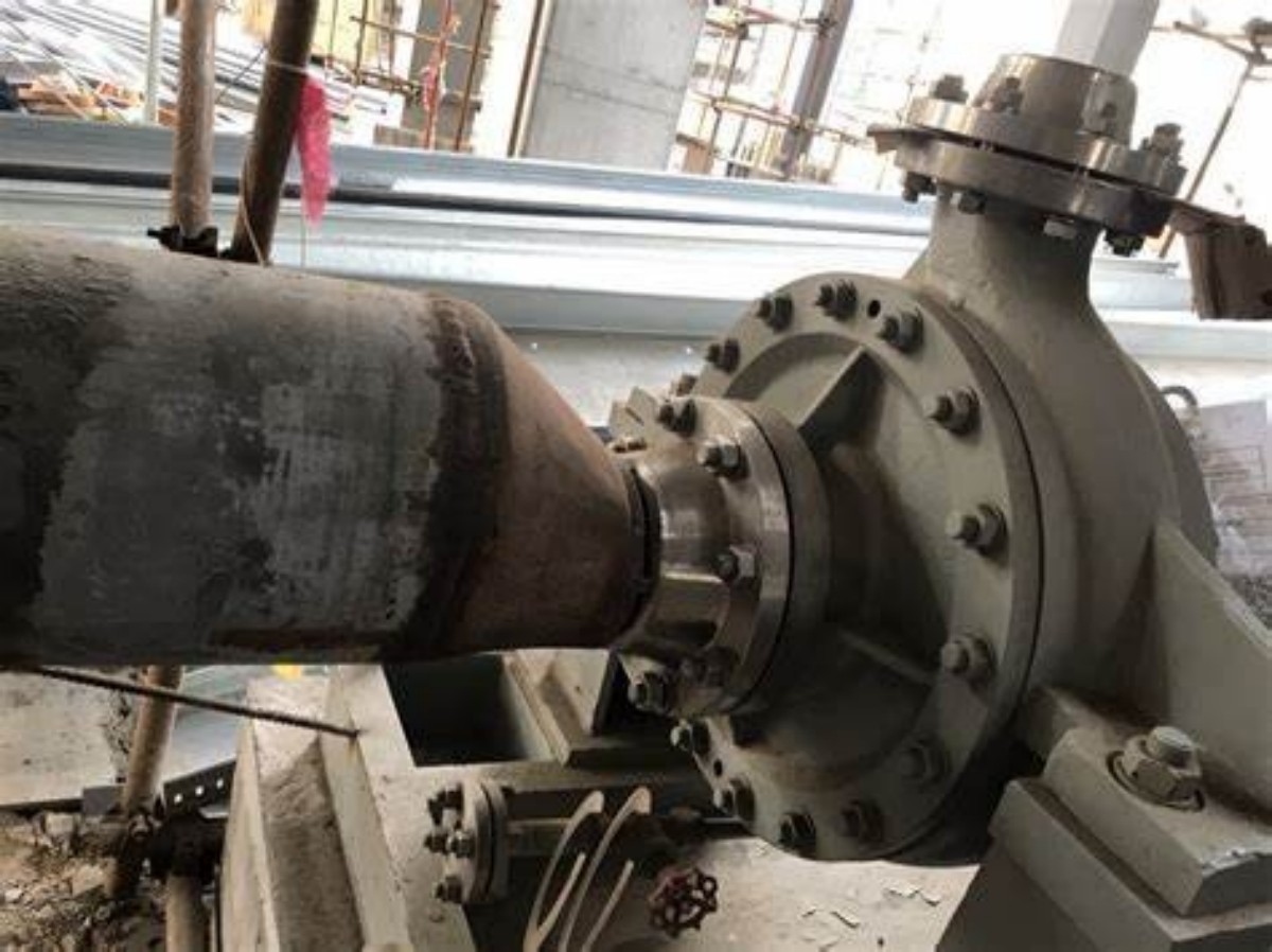
4.the installation direction definition standard
Defined using ASME Y14.5M Geometric Dimensions and Tolerances Standard:
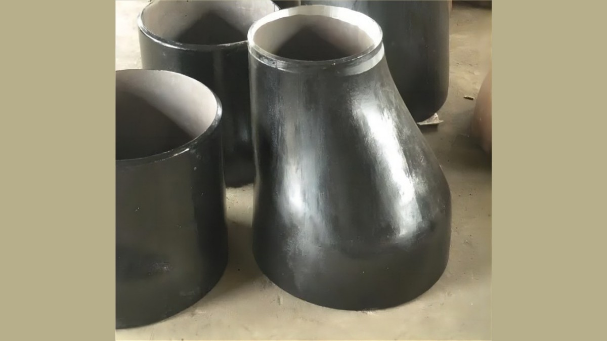
Top-flat installation: the plane of the eccentric part is flush with the inner wall of the pipe top
Bottom-flat installation: the plane of the eccentric part is flush with the inner wall of the bottom of the pipe
Note: In the actual project, it is recommended to use 3D laser scanning to verify the installation accuracy.
5.Suggestions for project implementation
Numerical simulation: Cavitation allowance (NPSH) analysis using CFD software
On-site verification: The homogeneity of the flow velocity distribution is detected by an ultrasonic flow meter
Monitoring program: Install pressure sensors and vibration monitors for long-term tracking
Maintenance strategy: Establish a regular inspection system to focus on the erosion of the inlet pipe section
The installation specification has been incorporated into ISO 5199 “Technical Specification for Centrifugal Pumps” and GB/T 3215 “General Technical Conditions for Centrifugal Pumps for Refinery, Chemical and Petrochemical Industries”.
Post time: Mar-24-2025